|
Appendix 2
: How to detect the internal audio error correction ability of a CD ROM drive
1 Introduction
The performance of CD ROM
drives and CD players reading some scratched or weared CDs depends on the quality
of their components, but also on the error correction performed by their
chipset. The audio data coming from the surface of the CD is converted into
binary information. It is divided in frames of 24 bytes each, that is 6 audio
samples. These frames pass through two layers of error correction. The first
layer is called C1. Thanks to the presence of 4 bytes of error correction
information, the chipset can correct up to two wrong bytes there. If there
are more than two wrong bytes at the C1 stage, the data is interleaved so
that the wrong bytes are scattered over different frames, and passed to the
C2 stage. There, there are three kind of strategies to correct errors. It is
possible to correct up to two wrong bytes in the C2 stage, up to three, and
up to four wrong bytes. When there are more wrong bytes, the chipset can't
correct the errors, so the wrong samples are replaced by a guessing of their
value, according to the neighborous samples, if they are themselves correct.
There is another possible difference between the error correction strategies
used. When the errors present in the C1 stage can't be corrected, it is
possible to flag all 24 audio bytes in the frame as wrong, because the C1
error correction is unable to sort the right and the wrong ones if too much
info is lost. But it is possible to keep track of the EFM decoding that
occured just before, so that only the ones that were already unreadable at
the EFM stage are flagged wrong. The other bytes that were properly read by
the EFM decoder are supposed to be correct. There is one chance out of 64
that they are wrong all the same, but the C2 stage will detect and correct
them anyway.
Last, there it is possible to come back to C1 again once the C2 error
correction is done, in order to take advantage of the info restored in the C2
stage for further error correction [5]
According to [7], the more wrong bytes we try to
detect, the less secure the error correction becomes. So when there are few
errors, it is better to use a weak error correction strategy, because it
ensures that errors are detected with more confidence. But when there are too
much errors, it’s better switching to a stronger strategy, because it may be
still possible to correct quite all of them. Better being a bit less sure
than everything is correct, but still get a perfect result most of the time,
than to be always sure to interpolate all errors, and get an average result
everytime.
We are going to detect
the kind of strategy used in a CD player to correct a big burst error.
2 The experiment
Analysing the C2 results
of the Memorex DVDMaxx 1648 on the DAEquality test CD, I came across this
graph (see the C2 results with the
DAEquality test CD) :
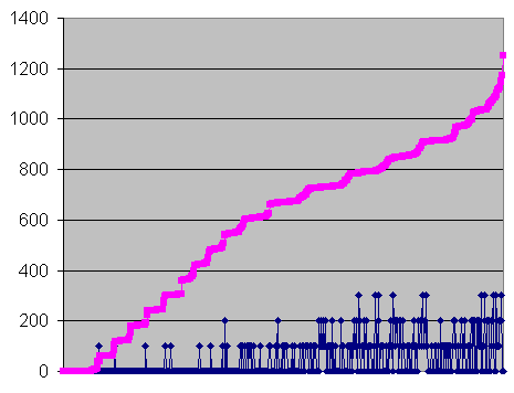
1 - Errors and undetected errors for each second in
the black mark range on the CD, without the peaks, sorted by number of errors
 Errors per second, for every second. Errors per second, for every second.
 Undetected errors per second x100 (here : 0, 1, 2, or 3) Undetected errors per second x100 (here : 0, 1, 2, or 3)
The first thing that
seems strange is the profile of the pink curve. It is expected to rise
evenly, but instead, it rises step by step. Here's a close-up :
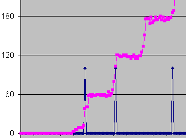
2 - Close-up on the three first steps of figure 1
The errors recorded each
second are mostly multiple of 60. Sometimes a little bit less. Why ?
I substracted the
extracted wave from the reference one, in order to look at the errors in a
wave editor. Looking at the resulting waveform, it was clear that errors came
always by isolated bursts of 60, and each burst had the errors at exactly the
same place. Sometimes one or two are missing, this is because the differences
being interpolated, their amplitude is very small, and some of them, by chance,
are equal to zero. Thus they are not visible.
Click here to
view a picture of the complete pattern for a 60 samples burst error. It is
543 samples wide from the first to the last error. Blue bars show the
differences between the extracted wave and the reference one. Each one shows
a wrong value in the copy. Right values are all the null samples in between,
that are the substraction of the copy from the original, thus zero if the
copy is the same as the original.
The horizontal axis marks are samples, and the vertical ones elementary 16
bits steps (maximum zoom).
The steps in the error
graph don't show up reading a bad CDR :
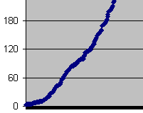
3 - Errors in a bad CDR, same settings as the pink curve of figure
2
The difference between
the test CD and a bad CDR is the distribution of the errors on the CD. On a
bad CDR, the errors occurs when the drive is unable to properly read the
data. Since the CDR is evenly weared on all its surface, the errors occurs
randomly. With the test CD, on the other hand, errors come from a little
black mark drawn on the surface, that makes about one milimeter of groove
completely unreadable, while the rest is perfect.
The CD is read at the linear speed of 1.2 meters per second, and the black
mark begins 31 millimeters from the center of the CD.
One rotation is
31*2*Pi=195 mm
Its duration is 195/1200=0.16 seconds, that is 7166 samples. So, at the
beginning of the errors, the elementary patterns should be spaced by at least
7000 samples, more if the errors begins further away in the black mark,
farther from the center of the CD.
In the wave, the first errors are at 301000 samples from each other. Then
164000, 284000... no need to try to divide these numbers by 7000, since more
than 20 rotations separate two of them. As the theoretical delay increases,
the inaccuray is too big.
Further in the wave, the errors are closer. An elementary spacing appears
between the bursts, that is about 9243 samples. That is 0.210 seconds, that
is about 250 millimeters, that is one rotation at 40 mm from the center of
the CD. This is still in the black mark. It's 2 mm wide at this place. So it
lasts 0.0017 seconds, that is 73.5 samples, that is 12 audio blocks.
So each time the black
mark is encountered, an error can occur, that is always exactly the same. It
must match the pattern of a given burst error on the CD, after CIRC decoding.
CIRC is the name of the
method used to encode PCM data, as it appears in wav files, that is 44100
stereo samples of 16 bits per second, onto audio CDs. I found two ressources
on the web explaining CIRC in detail, so that I could reconstruct the
observed pattern : Kelin Kuhn’s paper [1] and ECMA-130 specifications from ecma.ch [2]. It is advised to read one of them in order
to understand the following.
Kuhn's paper is better explained, but beware that is his text, C1 and C2 are
inverted !
In order to go on, you
will need the CIRC decoder diagram at hand, Fig C2 in ECMA 130. Beware that
the "delay of one byte" and "delay of two bytes" are in
fact delays of one and two frames respectively. What ECMA 130 calls
"F1 frames times" are in fact full frames, be them 24, 28, or 32
bytes. Top left; 328-bit bytes means "thirty two 8-bit bytes".
3 Image of a 16 frames EFM burst error with no EFM error detection and
4 bytes C2 correction
3.1
Error pattern in the C1 decoder
A CD player or a CD ROM
drive can correct up to two, three or four wrong symbols in a C2 frame,
according to the type of strategy used. It means, in the four wrong symbols
case, that if four bytes are changed in the C2 frames, it can always be
detected thanks to the additional information provided by the four parity
bytes, and if there are no more than four bytes affected in this frame, the
chipset can always calulate their original value and correct the error, be
them completely damaged.
As the errors we get come in clusters of 60 and not 5, is is possible that
the chipset doesn't use EFM information for error detection, because as soon
as a little part of a C1 frame becomes affected (3 or 4 bytes), 24 audio
bytes will be lost at once in the C1 stage. Maybe this will account for the
60 errors. Let's see what can happen.
The black mark masks
several consecutive frames of audio, on the CD, at the extreme left of the
CIRC decoder diagram (that stands for one frame only). I will call this
"CD" data "EFM", because the previous step that could be
shown on the left of the CIRC diagram is the EFM decoder.
These lost data, coming from the left of the diagram, pass through the first
delay line before reaching the C1 decoder. There, if more than 2 bytes are
wrong, generally, the whole frame is marked as wrong [4].
For an error to occur at the output, at least five bytes must be affected in
a C2 frame. But if only one C1 frame is destroyed, we can see that it will
affect only one byte in 28 different C2 frames. If four consecutive C1 frames
are destroyed, it will affect 1 byte in 112 consecutive C2 frames, and still
generate no error, since no C2 frame have more than one wrong byte. Therefore
our original EFM error, that is supposed to generate errors at the output,
must run longer than at least 2 frames, thus it includes at least one full
frame (and certainly more, but let’s see it step by step).
If it begins sooner than the byte number 27 in a given frame, the
corresponding C1 frame will have at least bytes 26, 28 and 30 affected, and
will be flagged as being all wrong. If it begins on byte 27 or later, the
corresponding C1 frame will have all its even audio bytes, from 0 to 26,
correct. It can be left all correct, or being flagged all wrong, because
bytes 28 and 30 are wrong [4]. The burst error being bigger than two
frames, the next C1 frame will have at least all its even bytes wrong (from
the next EFM frame), and be flagged all wrong.
Then, as the EFM error runs, all the subsequent C1 frames will be flagged
wrong.
The C1 frame corresponding to the EFM frame where the burst error stops will
have all its odd bytes wrong and will be flagged wrong. The next one can have
byte number 1 wrong, or unlikely 1 and 3, if the EFM burst error stops after
byte 0 and before byte 5.
Thus 95 % of the burst errors will affect an integer number of consecutive C1
frames (unlikely 90%) depending on where exactly it stops.
3.2
Minimal size of the error
We just saw that a burst
error such as the one on the DAEquality test CD, if EFM is not used for error
detection, will most of the time turn wrong all bytes in a given number of
consecutive C1 frames. Exept little glitches here and there in the data
returned by the Memorex drive, the smallest common error is a burst of 60
samples. Let's find the smallest number of wrong C1 frames capable of
creating uncorrectable errors.
It is easier to start from the CIRC encoder diagram (ECMA 130 fig C1), this
time. The C1 and C2 stages are the column "Generation of four parity
bytes". There is just one delay line between them, that drops one C2
byte every fourth C1 frame in the encoding process.
If we consider a situation in which we can correct up to four wrong bytes per
C2 frame, for an uncorrectable error to occur, at least one C2 frame must
have five wrong bytes. These bytes must all come from inside the affected C1
frames. For the C1 error to be the shortest, the 5 C2 bytes must be
consecutive ones. This way, they will be scattered across 17 C1 frames only.
If the first byte was in C1 frame 1, the second will be in C1 frame 5, the
next in frame 9, then 13, and 17.
Thus at least 17 C1 frames are wrong. This is the smallest common error.
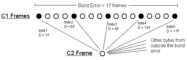
4 Gathering of five bytes from the C1 burst error in a C2 frame
3.3
Image of the error after decoding
A 17 frames C1 burst
error will not only generate 5 wrong byte in one C2 frame, but any serial of
consecutive bytes from frames 1, 5, 9, 13 and 17 will gather in a C2 frame,
and generate an uncorrectable error.
In order to compute the pattern of the resulting wrong samples, let's use
again a Microsoft Excel document. In the first column, write all the byte
sequences that will find themselves in the same C2 frame. The first one is 0,
1, 2, 3, 4. The next sequence of wrong bytes is 1, 2, 3, 4, 5, then 2, 3 ,4
,5 ,6 etc, until 23 , 24 , 25 , 26 , 27.
Then, in the Excel file, in the five next columns, write the delay affecting
each of the listed bytes in the first column, in mono samples, according to
the interleaving pattern between the C2 decoder and the final 24 bytes frame,
in the CIRC decoder diagram. One mono sample is 2 bytes. Two frames are 24
mono samples. For example, for bytes 0, 1, 2, 3, and 4, counting the first
sample as zero, it will be 0, 0, 4, 4 and 8.
In any sequence, the
first and last byte are in the first and last frame of the burst error.
Therefore the C2 frame in which they gather can be positionned relatively to
the first frame of the C1 burst error looking at the delay affecting the
first byte of each sequence. For example in the sequence 0, 1, 2, 3, 4, the
byte 0, according to the CIRC decoder figure, is delayed by 27D=27x4=108
frames between the C1 and the C2 stage. Write this delay in mono samples in
the next column.
Then, in the five next
column, add the sample positions with the frame delays. The 24x5=120
resulting numbers give the relative position of each wrong sample in the wave
file.
Paste all of them into another Excel file, sort them ascendingly and delete
all duplicates. Then in the next column, add an even constant so that the
first sample is 0 or 1, and divide by two in order to get the delays in
stereo samples. Since left and right samples are stored alternately, integer
numbers stand for the left channel, and decimal numbers for the right channel.
Here are the resulting
Excel files for two, three, and four C2 bytes correction
Delays
for a 17 frames C1 burst error (with five wrong C2 bytes)
Error pattern for a 17 frames C1 burst error (with five wrong C2 bytes)
Delays
for a 13 frames C1 burst error (with four wrong C2 bytes)
Error pattern for a 13 frames C1 burst error (with four wrong C2 bytes)
Delays
for a 9 frames C1 burst error (with three wrong C2 bytes)
Error pattern for a 9 frames C1 burst error (with three wrong C2 bytes)
The Memorex burst error
matches exactly the one predicted for the four wrong C2 bytes strategy. Since
the pattern features 60 samples spread over a range of about 1000 mono
samples, this result can't be the effect of chance. This drive corrected up
to four wrong bytes at the C2 stage of error correction, and most C1 frames
turned out flagged either all right, either all wrong.
We saw that the black mark covered about 12 frames. It means that the drive
didn't catch back the groove immediately after the black mark, but a little
further. Besides, we also saw that the first errors are spaced by about 20
rotations, therefore most of the time (19 times out of 20), the groove is
caught back before 17 C1 frames are lost and all errors are corrected.
The error can also be more than 17 frames, but this occurs further away in
the wave file, where the black mark is larger on the CD. Then the error
clusters get more and more complex, as the elementary patterns get mixed
together.
In conclusion, without
using EFM for error detection and correcting up to four wrong bytes at the C2
stage, the elementary burst error is 60 samples distributed like this :
0,5 2,5 4,5 24,5 26,5 28,5 48,5 50,5 52 72,5 74,5 76 96,5 98 100 120,5 122
124 144 146 148 168 170 172 192 194 216 218 240 264 279,5 303,5 325,5 327,5
349,5 351,5 371,5 373,5 375,5 395,5 397,5 399,5 419,5 421,5 423 443,5 445,5
447 467,5 469 471 491,5 493 495 515 517 519 539 541 543
Picture
Wave
file
Without EFM error detection
and correcting up to three wrong bytes at the C2 stage, the elementary burst
error is 52 samples distributed like this :
0,5 2,5 22,5 24,5 26,5 46,5 48,5 70,5 72,5 74 94,5 98 118,5 120 122 144 146
166 168 170 190 192 214 216 238 262 301,5 325,5 347,5 349,5 371,5 373,5 393,5
395,5 397,5 417,5 419,5 441,5 443,5 445 465,5 469 489,5 491 493 515 517 537
539 541 561 563
Picture
Wave
file
Without EFM error
detection and correcting up to two wrong bytes at the C2 stage, the
elementary burst error is 44 samples distributed like this :
0,5 2,5 24,5 26,5 46,5 48,5 70,5 72,5 94,5 98 118,5 122 144 146 168 170 190
192 214 216 238 262 325,5 349,5 371,5 373,5 395,5 397,5 417,5 419,5 441,5
443,5 465,5 469 489,5 493 515 517 539 541 561 563 585 587
Picture
Wave
file
4 Using EFM information
Before
the CIRC decoder, the data that comes from the CD pass through the EFM
decoder. There, each valid 14 bits symbols is converted into the matching 8
bits byte, according to the EFM table [2]. Since it is
possible to write 28=256 8 bits symbols, and 214=16384
14 bits symbols, only one 14 bits symbol out of 64 is used.
Thus when an error occurs, most of the time, the EFM decoder can’t find a 8
bits byte matching the erroneous 14 bits symbol. It is possible to take
advantage of this, and when three or four bytes are wrong in a given frame,
it is possible for the C1 decoder to correct them thanks to their position,
that is given by the EFM failures, while using only the P parity bytes, no
more than two wrong bytes can be corrected in the C1 stage. Furthermore, when
there are more than four errors in a frame, instead of marking all 28 bytes wrong,
it is possible to mark only the ones that the EFM decoder couldn’t translate.
As there is one chance out of 64 of generating a valid EFM symbol by
accident, we are not sure that all wrong bytes are marked wrong, but the C2
layer detects the missed errors. The advantage is not to overload the C2
decoder with suspicious bytes. When all bytes of a C1 frame are marked wrong,
some valid bytes that could be used for C2 error correction, if one frame has
only four wrong bytes, for example, are considered wrong all the same, and
the C2 frame having five bytes marked wrong instead of four, the error
correction is given up.
If a burst error
affecting N frames occurs on the CD, the C1 frames will keep track of most of
the errors detected by the EFM decoder. Because of the delay line between EFM
and C1, Each C1 frame keeps its even bytes, but receives the delayed odd
bytes from the previous one. Thus the first C1 frame got from the burst error
will have wrong odd bytes and right even bytes, all following C1 frames until
the Nth will have all bytes wrong, and the frame number N+1 will only have
the odd bytes wrong. Such C1 frames with every other byte wrong will be
refered to as “combed frames”.
But the error does not need anymore to affect an integer number of frames.
For example if it stops at the first quarter of a frame, the generated C1
frame will have all odd bytes wrong, because the previous EFM frame from
which they come was all wrong, plus the first quarter of the even bytes also
wrong. The next frame will just have the first quarter of the odd bytes
affected. Thus the burst error, once passed to the C1 level, will have a
combed pattern that is one frame long at both its ends, made of 16 even bytes
at the beginning, and 16 odd bytes at the end.
It changes the patterns computed above for strategies not using EFM info.
Without EFM info, once two or three bytes were wrong in a C1 frame, all the
frame was marked wrong, that’s why, as the burst error widens, the resulting
number of wrong samples at the output grew step by step : 60 when 17 C1
frames were affected, 120 when 18 were affected, 180 for 19, etc. Now, the
number of errors at the output is going to rise evenly as the burst error
widens, because the number of wrong C1 bytes will grow byte after byte instead
of frame after frame. This allows to detect easily if EFM information is used
for error detection.
In fig 4 above, we saw
that a C2 uncorrectable error comes from C1 frames spaced every 4 frames (for
our little burst error). The byte sequences taking part into the C2 error are
3, 4, or 5 bytes long according to the C2 error correction strategy, with
byte orders following each other. Thus the first and last byte orders, will
be of the same parity for 3 and 5 bytes sequences, and of an opposite parity
for 4 bytes sequences. Those bytes are at the beginning and at the end of the
error. Thus if we consider an EFM error with the smallest necessary number of
frames in order to generate a C2 error, those bytes will be into the combed
parts in the C1 stage. EFM errors of 8, 12, and 16 frames will generate C1
errors of 9, 13, and 17 frames, but with the first and the last ones combed.
Since the last C1 erroneous frame will have the odd bytes affected while the
first will have the even ones, the result will depend on the parity of the
first and last byte in the sequence generating the C2 error.
If the parity is the same (sequences of 3 or 5 bytes), when the first byte of
the sequence is wrong (even position), the last is right (still even
position), and conversely. Thus no C2 error is generated. Let’s see what
happens if one more frame is wrong. Every sequence beginning with an even
byte is wrong, because now, the last frame of the last byte of the sequence
is completely wrong. But it is also true for sequences beginning in the
second frame, and finishing with an odd byte.
Let’s add another column in the Excel file, with an additional delay of 12
mono samples for sequences beginning with an odd byte. Here are the results :
Delays
for a 9 frames EFM burst error (with three wrong C2 bytes and using EFM info)
Error pattern for a 9 frames EFM burst error (with three wrong C2
bytes and using EFM info)
Delays
for a 17 frames EFM burst error (with five wrong C2 bytes and using EFM info)
Error pattern for a 17 frames EFM burst error (with five wrong C2
bytes and using EFM info)
We can see that they look
like the ones without the use of EFM info, but with every other group of
three wrong samples shifted one frame (6 stereo samples) to the left.
The case with four wrong bytes is different, because, as the first and last
byte of each sequence have opposite parities, when only 12 EFM frames are
affected, the wrong byte sequences beginning in the first combed C1 frame
will also finish on wrong bytes in the 13th frame, that is also
combed. Thus in this case, we will get half of the sequences that are wrong
without using EFM info. Here is the resulting pattern :
Delays
for a 12 frames EFM burst error (with four wrong C2 bytes and using EFM info)
Error pattern for a 12 frames EFM burst error (with four wrong C2
bytes and using EFM info)
Unlike the previous
patterns got when EFM info is not used, these patterns won’t happen often as
they are given. The burst errors actually occuring in the output file will be
shorter at the beginning, showing only little parts of the pattern linked
above, because the burst error won’t reach the total number of needed frames
at once. The first frame that generates errors (the 9th, 12th,
or 17th) will be progressively filled, byte after byte, generating
error patterns bigger and bigger, until it reaches the size matching the
given patterns, and the burst will go on after that. It is even quite
possible for these patterns never to appear exactly, since the burst error
can rise from just less than the needed number to just more.
This is valid if the
burst error starts and stops at frame boundaries. What will happen if it is
offsetted by half a frame, for example ? The first C1 frame will have its
second half combed, that will match the second half of the previous last C1
frame. About half of the pattern above will appear (the first half, since the
delays diminish as the byte order increases). The next C1 frame, that was
fully affected, but did not take part in any C2 error, will have its first
half combed, and will have a new C1 frame after the previous last frame that
will also have its first half combed, so about the second half of the pattern
will appear too, but offsetted 6 stereo samples to the right.
5 Peforming double pass
There
may another strategy to perform CIRC decoding : double pass [5].
Once the C2 error correction is done, the data goes back into the delay line
and the C1 and C2 error corrections take place again. This allows to correct
errors that were uncorrectable in the first pass.
For example, imagine a random error consisting in five C1 frames, spaced 4 by
4, each of them having just the lowest number of uncorrectable bytes, e.g.
three, that is a total of 5x3 = 15 wrong bytes, instead of being all wrong.
Now imagine that 5 of them, one from each frame, gather all in the same C2
frame, while the others are scattered into other frames. In the single pass
strategy, this C2 frame have an uncorrectable error, with at least 3 samples
affected. But if the data is sent back to C1, all other bytes having been
sent into other C2 frames have been corrected in the meantime, now the only
wrong bytes left in the second C1 pass are the five ones that were in the
same C2 frame, and each of them is now back into its own C1 frame, where it
is the only bad byte left. Each of these C1 frame having just one wrong byte,
they can now be corrected, and there is nothing left wrong at all. The C2
error doesn’t occur anymore in the second C2 pass, since the C1 level doesn’t
send anymore wrong bytes. In this case, performing a double pass allowed to
correct an uncorrectable C2 error.
In the case of a burst
error, it will be difficult to see the difference with single pass. If the
second C1 pass is the same as the first, nothing will change, so the system
only works when the second C1 pass allows to correct C1 frames that were
previously uncorrectable, and only the first C2 pass can make the difference.
Therefore, the C1 frame must generate at most 1, 2 or 4 uncorrectable C2
errors, according to the error correction strategy. Otherwise, more wrong
bytes will be left after the first C2 pass, and the C1 frame won’t be
corrected in the second pass, leading to the same results as the first time.
The bytes corrected in the first C2 pass will just be replaced at their
position in the second C2 pass, not changing anything from the first C2 pass.
Thus the difference can only exist for C1 frames implied into less than five
uncorrectable C2 errors.
5.1
Effect if EFM info is not used
Not using EFM info, with
the minimal burst error studied above, each C1 frame involved into C2 errors
generates 24, 25, or 26 of them, according to the C2 error correction
ability. If the burst error is bigger, this number can rise to 28, if every
byte is involved into a C2 error. Thus, this number being far above the
required 1 or 2, the double pass strategy doesn’t change anything to burst
error handling in this case.
5.2
Effect using EFM info
Using EFM information,
there can be some C1 frames involved into less than five C2 frames. In these
C1 frames, after the first C2 pass, all bytes will be corrected exept the
ones that were in the C2 errors. Since every C1 byte goes into a different C2
frame, there can be no more than four bytes affected in this C1 frame. Thus,
granted, as [6] suggests, that 4 wrong bytes can be
corrected in a C1 frame knowing their positions, the frame can be corrected,
and generates no more C2 errors.
In the case of minimal C2 errors (no more than 3, 4, or 5 wrong bytes in a C2
frame), no C1 frame can generate more than 0 and less than 5 C2 errors after
the two passes. As a C1 frame can usually generate 1 to 28 C2 errors, with
the burst error boundary being anywhere inside a frame, the effect on the error
patterns will be hardly visible, lost into the patterns of various sizes that
the regular one pass mode already generates. In order to see it, I think that
it would be necessary to compute all possible error patterns for little burst
errors (that is for a burst error size increasing byte by byte), list their
sizes, and point out the sizes that should be missing in the double pass
strategy. Then the effect might be visible in a graph such as the one figure
2 above, that stands for no use of EFM, and correcting 4 C2 bytes.
6 References
[1] Audio Compact Disk, an
introduction,
Kelin Kuhn
[2] ECMA-130 Compact Disc Standard
[3] Info about chipsets
provided by BobHere
[4] Info about C1 error detection provided by BobHere and Spath
[5] Existence of double
pass CIRC strategy mentioned by BobHere
[6] C1 error correction, Writing
quality article, page 9, CDRinfo.com
[7] Why
switching between different CIRC strategies ?, by BobHere, according to
Pohlmann.
Home
Version
4 By Pio2001, updated february the 6th, 2003
Version 1 created december 2002
|